Solutions
CupLock Calculator
The CupLock MTO calculator turns a floor into a material take-off: how many standards, ledgers, jacks, beams and accessories you need to shore it. It checks the grid is safe for the slab, shows the shoring in 3D, and puts the quantities straight onto your building's material list.
Two ways to start
Recommended
From your project
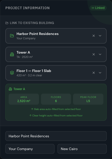
Open it from a building or a floor. The project, building and floor are linked, the floor's area, clear height and thickness are filled in, and you can assign the result to your floors in one click.
Quick estimate
On its own
Open Solutions → CupLock Calculator and type the numbers in. Good for a tender or a quick check. You can still link a building later from the same page.
Open it from your project
If the project, building and slabs are already in PlyMax, don't type their numbers again. Open the calculator from where the data lives and it arrives filled in.
| Where you are | What to click | What gets linked |
|---|---|---|
| A building's Materials page | Cup Lock MTO (next to Add from Library) | Project and building. Pick the floor in the calculator |
| A building's Materials page, floor chips | A floor without materials (F2 ○), then CupLock MTO | Project, building and that floor |
| The Tracker, a slab's shoring panel | Open in CupLock → | Project, building and that floor |
The calculator then fills in:
| Field | Taken from |
|---|---|
| Project, company and location | From the project and building |
| Area | The selected floor's slab area. Before you pick a floor: the building's average area per floor |
| Clear height | The selected floor's clear height, as set in the Tracker |
| Slab thickness | The selected floor's slab thickness |
Set clear heights in the Tracker first
You can also link by hand on the calculator page: under Link to Existing Building, choose the Project, the Building and the Floor / Slab. Each floor in the list shows its area and clear height, and whether it already has CupLock materials.
A linked building needs a floor
Run a calculation
Check the slab zone
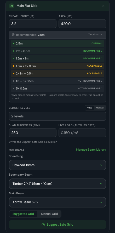
Every calculation starts with one slab zone, Main Flat Slab. Rename it if you like. Enter the Clear Height (floor to slab soffit, in metres), the Area in m² and the Slab Thickness in mm. If you opened the calculator from your project, these are already filled in. The Live Load follows from the thickness (BS 5975) and can't be edited.
Pick how the standards stack
Under the height fields, the calculator recommends the standards that make up each leg, e.g. Recommended: 2.5m. Open the list to see every combination that fits, ranked from Optimal to Not Recommended. Fewer pieces means fewer joints: a stiffer leg that is faster to erect. Click an option to use it.
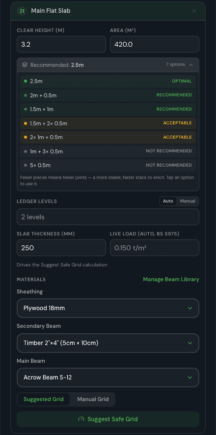
Ledger Levels is worked out from the height. Switch it to Manual only if your method statement calls for a set number of levels.
Choose the materials
Pick the Sheathing, Secondary Beam and Main Beam. They set the build-up between the U-head and the slab (the soffit height), and they are what the safe-grid check uses. The lists come from your beam library, the same one the Falsework Calculator uses.
Click Suggest Safe Grid
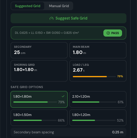
The calculator sizes the grid for this slab and shows the load breakdown, a PASS or FAIL, the secondary and main beam spacings, the shoring grid, and the load on each leg against its 3.4 t capacity.
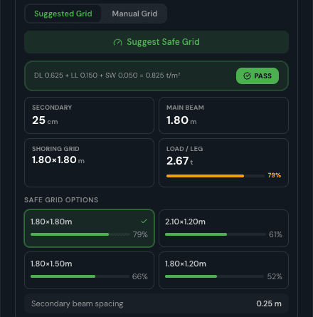
Under Safe Grid Options, pick any grid that suits the ledgers you have. Every option has passed the checks; the bar shows how much of the leg capacity it uses.
Click Calculate MTO
The results open on the right, on the Materials tab.
Input reference
Slab zone
| Field | What to enter |
|---|---|
Zone label Optional | A name for the zone, shown in the results and the Excel file. |
Clear Height (m) Required | Floor to slab soffit. Sets the standards, jacks and ledger levels. |
Area (m²) Required | The plan area to shore. Sets the number of standards and ledgers. |
Standards stacking Optional | The standard lengths per leg. Recommended automatically. |
Ledger Levels Optional | Auto from the height. Manual to set your own count. |
Slab Thickness (mm) Required | Drives the load, and so the safe grid. Pre-filled with 250. |
Sheathing / Secondary Beam / Main Beam Required | Pre-selected. Shared by all zones. |
Grid Required | Suggested Grid (checked for you) or Manual Grid (your own X and Y). |
Advanced options
| Field | What to enter |
|---|---|
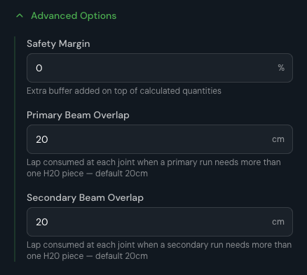
Safety Margin (%) Optional | Extra quantity added on top for losses and breakage, 0–20%. Shown as Wastage in the results. Default 0. |
Primary Beam Overlap (cm) Optional | Length lost at each joint where a primary beam run needs more than one piece. Default 20. |
Secondary Beam Overlap (cm) Optional | The same, for secondary beams. Default 20. |
Available sizes, listed at the bottom of the input panel:
| Component | Sizes |
|---|---|
| Standards | 0.5, 1.0, 1.5, 2.0, 2.5, 3.0 m |
| Ledgers | 0.6, 0.9, 1.2, 1.5, 1.6, 1.8, 2.1, 2.4, 2.7, 3.0 m |
| P-Head (base jack) | 5 – 35 cm extension |
| U-Head | 10 – 35 cm extension |
Manual grid
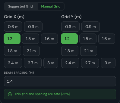
To use a grid of your own, switch to Manual Grid and pick Grid X and Grid Y from the ledger lengths, then enter the Beam Spacing (secondary beams, in metres). The calculator checks it straight away.
Don't ignore a red result
Zones and beams
A floor is rarely one flat slab. Add more zones under the zone list:
- + Slab Zone: another area with a different height, thickness or grid, e.g. a double-height lobby. It starts with the last zone's values. The total area of all slab zones is shown next to the buttons.
- + Beam Zone: the props under a downstand beam, measured by length instead of area.
Beam zones
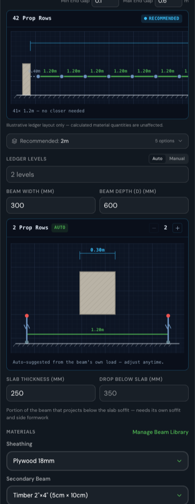
Enter the beam's Total Length, Beam Width and Beam Depth (D). The calculator works out the Drop Below Slab (depth minus slab thickness) and, in Auto, the Clear Height to Soffit under the beam (the slab's clear height minus the drop). It also suggests how many Prop Rows to put across the beam's width; use the − / + buttons to change it.
| Option | What it does |
|---|---|
| Total Length · On | Enter several separate beam runs instead of one length. Paste a column from Excel into Edit Beam Lengths. |
| Min / Max End Gap | The smallest and largest gap allowed between the last ledger and the column face, for the layout sketch. |
| Multi-Length | Tick the ledger lengths you have in stock. The calculator fits them exactly between the columns. |
The sketches show how the ledgers sit along the beam. They are for setting out only; they don't change the quantities.
Reading the results
At the top: the project, date, safety margin and number of zones, then four totals: Standards, Ledgers, Beams (LM) in linear metres, and Accessories. Below them, three tabs.

Materials
Every item, grouped into Standards, Ledgers, Beams and Accessories. Net Qty is what the design needs; Wastage is your safety margin; Order Qty is what to order. With several zones, switch between each zone and the grand total.
3D View
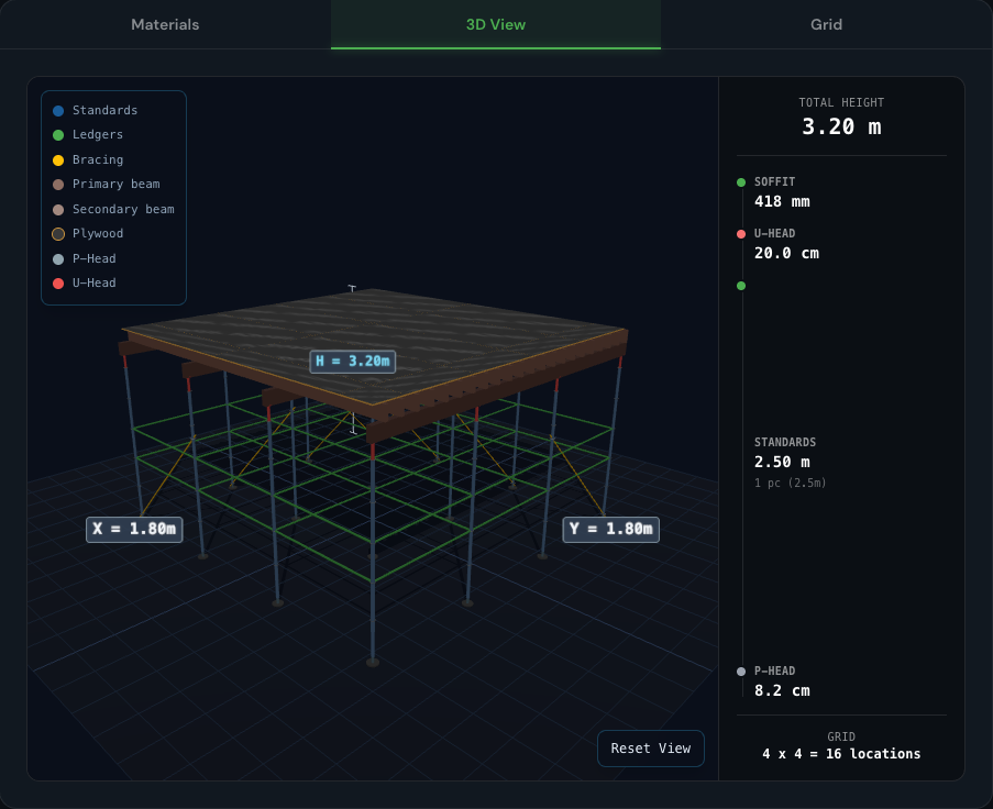
The shoring as built, with a legend for each component. Drag to rotate, scroll to zoom, and click Reset View to start again. The panel on the right breaks down the height: soffit build-up, U-head, standards and P-head.
Tip
Grid
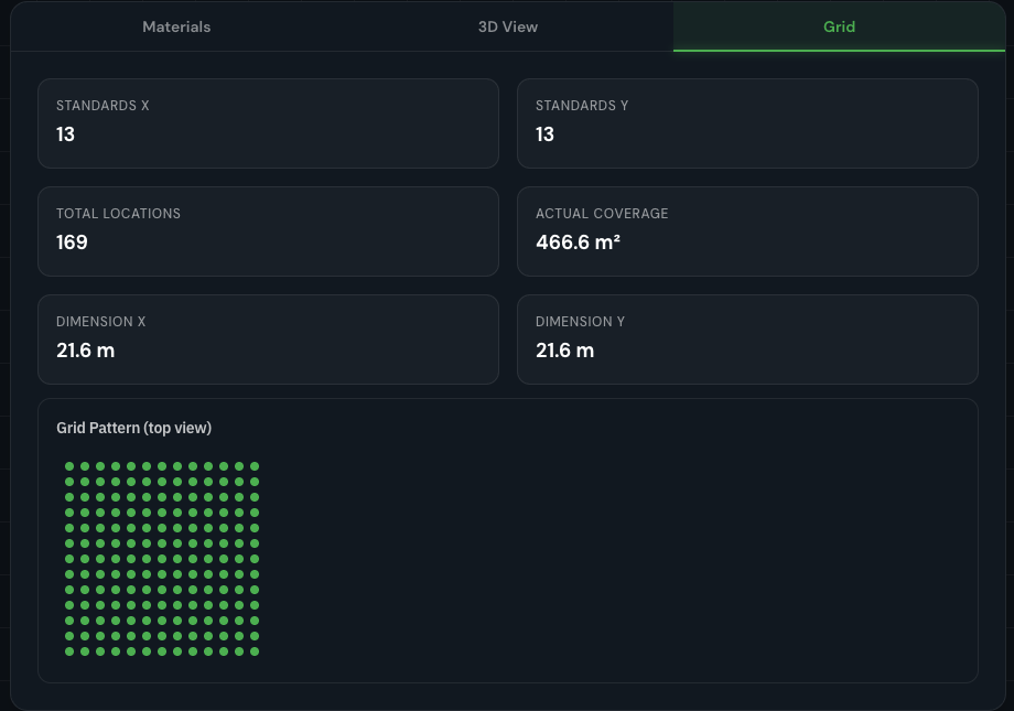
Standards along each side, total leg locations, the area actually covered (rounded up to whole bays) and a top-view dot plan of the legs.
Assign to your floors
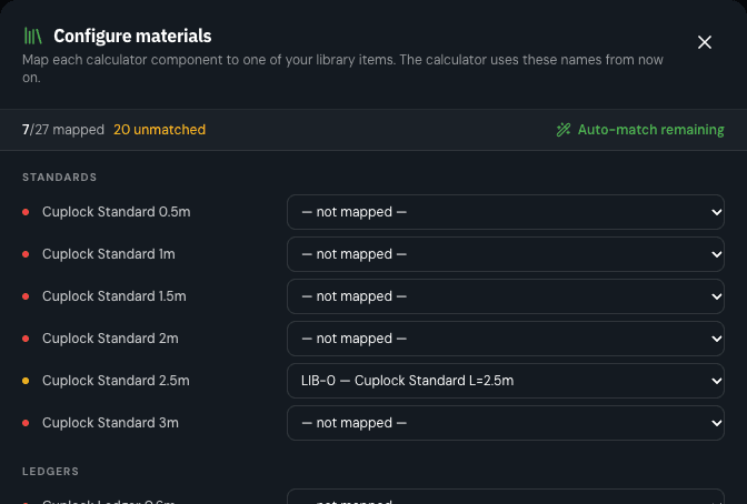
When the calculator is linked to a building, the result can go straight onto the building's material list. Each item needs to match an item in your material library first.
Map any unmatched items
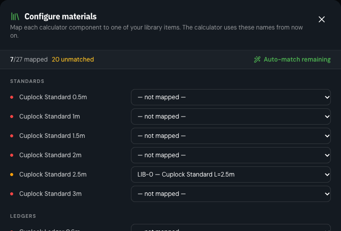
If some items don't match your library, a yellow notice lists them. Click Configure materials and pick your library item for each calculator component, or click Auto-match remaining. Click Save mapping. The calculator remembers it for next time.
Click Assign to Floor
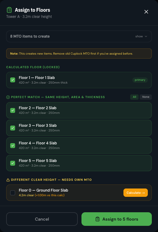
The button names the floor, e.g. Assign to Floor 1 — Floor 1 Slab. PlyMax then suggests other floors the same quantities fit.
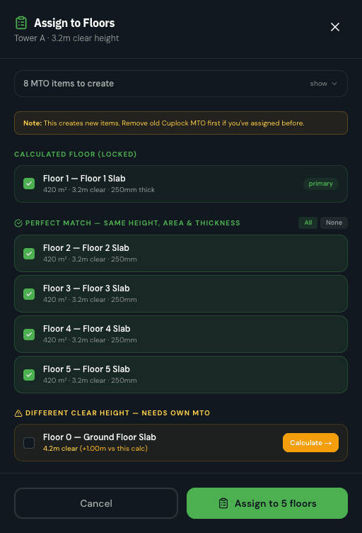
Group Meaning Ticked? Calculated floor (locked) The floor you calculated. Always Perfect match Same clear height (±0.1 m), area (±5%) and thickness (±5 mm). Yes Same height — area or thickness differs Same legs, but the counts would differ. No. Tick only if you accept that Different clear height — needs own MTO Different standards. Click Calculate → to run that floor. No No clear height set PlyMax can't compare it. Check before ticking. No Click Assign to N floors
The items are added to each floor on the building's Materials page, and those floors show as covered (F1 ✓). Use Back to Materials at the top of the calculator to return.
Assigning adds, it doesn't replace
Assigning again creates a second set of items. Remove the old CupLock MTO from the floor first.
Save and export
- Save Calculation keeps the inputs and results. Open them again from Calculation History at the top of the page, where you can search, sort and delete.
- Excel downloads the material take-off as a workbook to send to your supplier or store.
- Reset clears the zones and settings back to the defaults.
Plans and limits
On the free trial you get 5 MTO calculations a month; a bar above Calculate MTO shows how many are left. Each click on Calculate MTO counts as one. Suggest Safe Grid doesn't count. Paid plans have no monthly limit.
Troubleshooting
| Field | What to enter |
|---|---|
Calculate MTO is greyed out Optional | A building is linked but no floor is selected. Pick one under Floor / Slab. |
No Assign button Optional | Either no building and floor are linked, or some items aren't mapped yet. Use Configure materials. |
Clear height didn't fill in Optional | The floor has no clear height. Set its levels in the Tracker, or type it in. |
FAIL on the safe grid Optional | The slab is too heavy for the grid. Pick a tighter option or a stronger main beam. |
Quantities look high Optional | Check the Safety Margin in Advanced Options, and that the area is one floor, not the whole building. |
An estimate, not a sign-off