Solutions
Falsework Calculator
Enter a slab thickness and pick your materials. The calculator works out how far apart the secondary beams, main beams and shoring legs can be, checks each layer for bending, shear and deflection, and checks the load on every leg.
How it works
Slab falsework is a stack of four layers. The calculator designs them from the top down: each layer's strength decides how far apart the layer under it can be.
Sheathing
The plywood or boards the concrete sits on. It spans between the secondary beams.
Decides: Secondary beam spacing
Secondary beams
Timber or aluminium beams under the sheathing. They span between the main beams.
Decides: Main beam spacing
Main beams
Heavier beams that sit in the shoring heads. They span between the legs.
Decides: Leg spacing (shoring grid)
Shoring legs
Cuplock standards or Doka props that carry everything to the floor below.
Decides: Load per leg vs. capacity
Open it from Solutions → Falsework Calculator. You need to be signed in. The calculator is a stand-alone tool: it doesn't read or change your projects, so you can use it before a project exists.
Run a calculation
Enter the slab thickness
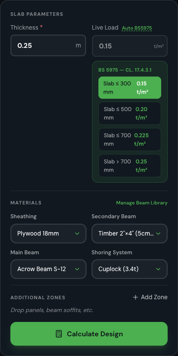
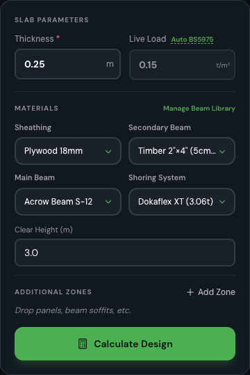
Type the slab thickness in metres: 0.25 for a 250 mm slab. It's the only required field. The Live Load fills itself in from the thickness, following BS 5975 clause 17.4.3.1. Click Auto BS5975 to see the table it uses.
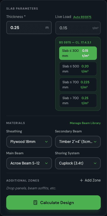
The input panel, with the BS 5975 live load table open. Metres, not millimetres
Typing 250 means a 250 m slab, and every result will fail. Use 0.25.Choose the materials
Pick the Sheathing, Secondary Beam and Main Beam you have on site, and the Shoring System. The defaults (Plywood 18mm, Timber 2"×4", Acrow Beam S-12 and Cuplock) suit a typical slab, so you can calculate straight away and change them later. The lists come from your account's beam library. See Beam library.
Add zones, if the slab has drops or beams
Optional. If part of the slab is deeper, such as a drop panel or the soffit of a beam, add it as a zone so it is checked too. See Zones.
Click Calculate Design
The results appear on the right. A green PASS means every layer and the legs are within their limits for the spacings shown.
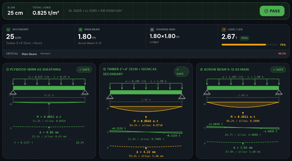
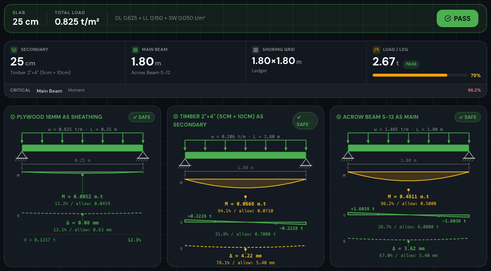
A 250 mm slab: 25 cm secondary spacing, main beams at 1.80 m, a 1.80 × 1.80 m grid, 2.67 t per leg.
Input reference
| Field | What to enter |
|---|---|
Thickness Required | Slab thickness in metres (0.25 = 250 mm). Sets the concrete load and the live load. |
Live Load Optional | Read-only. Taken from BS 5975 by thickness; see the table below. |
Sheathing Required | The deck the concrete is poured on, e.g. Plywood 18mm. Pre-selected. |
Secondary Beam Required | The beams directly under the sheathing, e.g. Timber 2"×4". Pre-selected. |
Main Beam Required | The beams that sit in the shoring heads, e.g. Acrow Beam S-12. Pre-selected. |
Shoring System Required | Cuplock (3.4 t per leg), Dokaflex XT (3.06 t per prop) or Dokaflex 20 (2.04 t per prop). Pre-selected: Cuplock. |
Clear Height Optional | Doka systems only. Floor to soffit, 1.5 – 6.0 m. Taller props carry less, so this changes the prop capacity. |
Additional Zones Optional | Deeper parts of the slab (drop panels, beam soffits) to check alongside the main slab. |
Live load by slab thickness (BS 5975, clause 17.4.3.1):
| Slab thickness | Live load |
|---|---|
| Up to 300 mm | 0.15 t/m² |
| 301 – 500 mm | 0.20 t/m² |
| 501 – 700 mm | 0.225 t/m² |
| Over 700 mm | 0.25 t/m² |
Reading the results
The results panel has four parts, top to bottom.
- Load banner. The slab thickness, the Total Load it puts on the falsework, how that total is made up, and the overall PASS or FAIL.
- Spacing tiles. Secondary is the distance between secondary beams. Main Beam is the distance between main beams. Shoring Grid is the leg layout, along × across. Load / Leg is what each leg carries, with a bar showing how much of its capacity is used.
- Critical. The single check closest to its limit, e.g. Main Beam · Moment · 96.2%. This is the layer to watch if you change anything.
- Beam diagrams. One per layer, showing the load on it (w), its span (L), and the bending moment (M), shear (V) and deflection (Δ) next to what the section allows.
Where the total load comes from
Concrete (DL) = thickness × 2.5 t/m³ = 0.25 × 2.5 = 0.625 t/m²
Live load (LL) = from BS 5975 table = 0.150 t/m²
Formwork (SW) = fixed allowance = 0.050 t/m²
Total load = 0.825 t/m²
Load on each leg
Load / leg = total load × main beam spacing × leg spacing
= 0.825 × 1.80 × 1.80 = 2.67 t (79% of 3.4 t)
Utilisation colours
Every bar shows the applied value as a percentage of the allowable one.
| Colour | Utilisation | Meaning |
|---|---|---|
| Green | Below 75% | Comfortable margin. |
| Amber | 75 – 90% | Safe, with a smaller margin. |
| Red | 90 – 100% | Safe, but close to the limit. Check the site conditions match the inputs. |
| Red + FAIL | Over 100% | Not safe at these spacings. Tighten the spacing or use a stronger section. |
How spacings are chosen
Each layer is checked three ways: bending (moment), shear and deflection. Whichever allows the shortest span governs.
- Secondary spacing is 25 cm when the total load is up to 1.5 t/m², and 20 cm above that. If the sheathing can't span that far, the calculator uses the largest of 20, 25, 30, 40, 50 or 60 cm that it can.
- Main beam and leg spacings are rounded down to a standard ledger length: 0.60, 0.90, 1.20, 1.50, 1.80, 2.10 or 2.40 m.
- If the load on a leg would exceed its capacity, the leg spacing steps down a ledger size until it fits.
- Deflection limits: the sheathing uses the limit stored for that section in the library; beams use span ÷ 333; overhanging ends (cantilevers, up to a third of the span) use span ÷ 180.
Design options
Below the diagrams, Design Options lists other safe layouts for the same slab. Click one to make it active: every figure, diagram and the PDF switch to it. Click it again to go back to the default.

| Option | What changes | When to use it |
|---|---|---|
| A · Optimized | Every layer at its calculated limit. The default. | Standard practice; balanced material use. |
| B · Conservative | Recalculated from a 15% tighter sheathing span. | Better slab finish, more margin on the deck. |
| C · Economic | The next wider ledger for the legs, only if leg use stays under 85%. | Fewer legs and faster erection. |
| C · High Load | Shown instead of Economic when that isn't possible: a tighter main beam grid. | Heavy loads, weak ground, stacked falsework. |
| Others | Common site grids, such as 1.20 × 1.80 m, when they pass. | Matching the ledgers you already have. |
Every option shown has passed
Custom option
To try your own spacings, open Custom Option. Enter the Secondary spacing in cm and the Main Beam and Leg (Grid) spacings in m, or click a Leg preset. The checks update as you type: moment, shear and deflection for each layer, the longest overhang each beam can take, and the leg load.
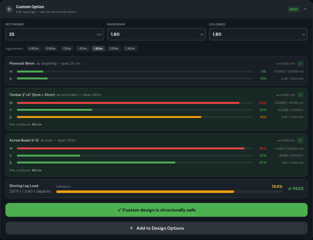
When the whole layout passes, click Add to Design Options. It joins the list as Custom 1, Custom 2… and can be made active and exported like any other option. A failing layout can't be added.
Tip
Calculation breakdown
Click Calculation Breakdown to see the working for the active option. Each step shows the layer, the spacing it set, what governed it, and its highest utilisation. Expand a step for the load on it (w), the moment, shear and deflection bars, and the overhang check.
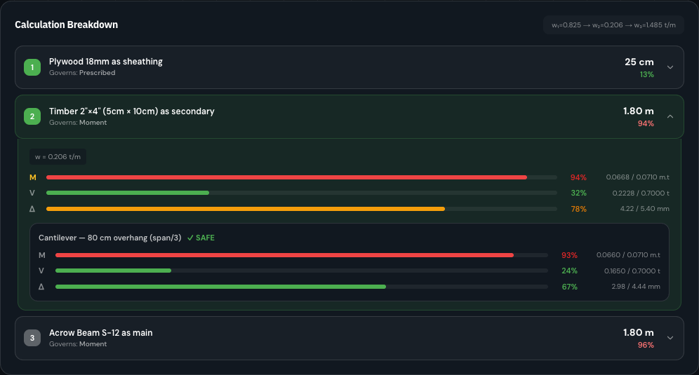
Governs: Prescribed on step 1 means the 25 cm (or 20 cm) rule set the spacing, not the sheathing's strength.
Zones
A slab is often not one thickness. Click Add Zone and choose a type. You can rename a zone and change its thickness in metres.
| Zone type | Starting thickness |
|---|---|
| Drop Panel | Main slab + 0.15 m |
| Beam Soffit | 0.60 m |
| Custom | 0.30 m |
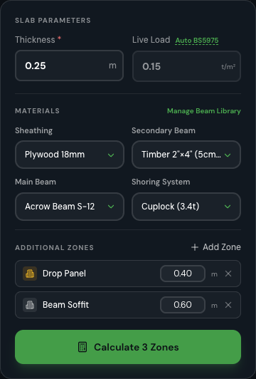
The button now reads Calculate 3 Zones. Each zone is designed on its own, and a Zone Comparison table appears under the results. The zone with the tightest grid is marked GOV (governing), and Unified Grid gives the one layout that works everywhere.
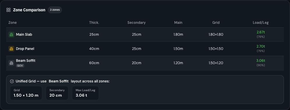
One grid or several?
Doka Dokaflex
Choose Dokaflex XT (Eurex 20 TOP props, 3.06 t) or Dokaflex 20 (floor props, 2.04 t) as the shoring system and a Clear Height field appears. Enter the floor-to-soffit height.
Doka systems are not calculated layer by layer. The spacings come from Doka's own design tables (EN 12812), so the diagrams, design options, custom option and breakdown are not shown. Instead you get Design Details: the secondary (c), primary (b) and prop (a) spacings, the prop capacity at your clear height, the load and area per prop, and site recommendations.
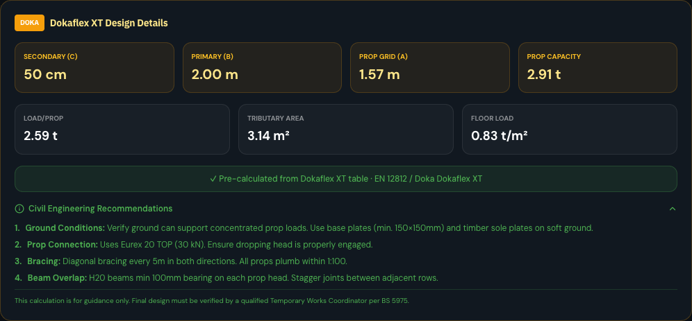
Taller props carry less
Beam library
The sheathing and beam lists come from your account's library. Click Manage Beam Library to see the structural values behind each section: area (A), second moment of area (I), section modulus (Z), stiffness (E), allowable moment (M_all) and shear (Q_all), width and deflection limit. Add a section to use a beam your supplier stocks.
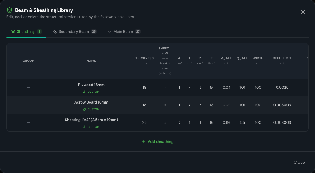
Library values drive every result
Export a PDF
Pick the option to export
Click the design option you want. The PDF uses the active option, including a custom one.
Click Export PDF
Add a Project Name and Company Name if you want them on the cover; both are optional. Leave Save to calculation history ticked to keep a copy under Dashboard → Calculations.
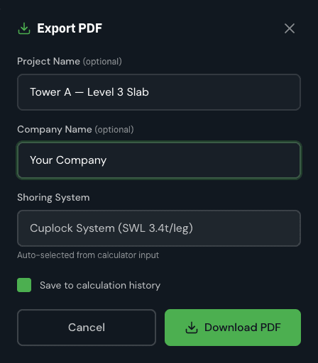
Click Download PDF
The report downloads with the inputs, loads, spacings, every check and, for multi-zone runs, the zone comparison. The file is named after the project, thickness and date, e.g. PlyMax_Tower_A_25cm_2026-11-02.pdf.

Plans and limits
On the free trial you get 5 calculations a month. A counter next to the title shows how many you've used, and it resets on the 1st. Each click on Calculate Design counts as one, however many zones it includes. Paid plans have no monthly limit.
Troubleshooting
| Field | What to enter |
|---|---|
Everything fails Optional | Check the thickness is in metres (0.25, not 250). |
FAIL on the legs Optional | The slab is too heavy for the grid. Pick a tighter design option, a custom leg spacing, or a stronger main beam. |
A beam is red Optional | Reduce the span of that layer: tighter main beam spacing for secondary beams, tighter leg spacing for main beams. |
No options for Doka Optional | Expected. Doka spacings come from Doka's tables; see Design Details. |
A section is missing Optional | Add it in Manage Beam Library with values from the supplier's data sheet. |
Guidance, not a sign-off